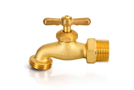
In refrigeration systems, copper pipes are one of the most commonly used materials. Copper pipes have advantages such as good thermal conductivity, high strength, good plasticity, and corrosion resistance. They are widely used in heat exchange components such as condensers and evaporators, as well as in connection pipelines. This article will provide a detailed explanation of the classification of copper pipes, technical requirements for copper pipes used in refrigeration, and the calculation of copper pipe wall thickness.

Classification and Performance Characteristics of Copper Pipes
By material composition
Copper pipes can be classified into pure copper pipes (TP2), brass pipes (H62/H65/H68), bronze pipes (QSn6.5-0.1), and cupronickel pipes (Ni-Cu alloy). Among these, pure copper pipes have the best thermal conductivity but are relatively expensive; brass pipes have high strength but low thermal conductivity; bronze and cupronickel pipes have good corrosion resistance but poor workability.
By production process
Copper pipes can be classified into oxygen-free copper pipes, oxygen-containing copper pipes, and inner-grooved copper pipes. Oxygen-free copper pipes have high purity and are generally used to make capillary tubes and other precision components; oxygen-containing copper pipes have moderate strength and hardness, good weldability, and are often used as connection pipes; inner-grooved copper pipes have grooves on the inner wall, achieving good enhanced heat transfer effects.
By hardness
Copper pipes can be classified into three types: soft temper (O temper), half-hard temper (1/2H), and hard temper (H temper). O temper copper pipes are soft and have good plasticity and ductility but low strength; H temper copper pipes have high strength and hardness but poor plasticity; 1/2H copper pipes have moderate strength and plasticity, with good workability and are the first choice for refrigeration pipelines.

Technical Requirements for Copper Pipes Used in Refrigeration Systems
Material Requirements
Refrigeration systems mostly use 1/2H temper pure copper pipes (TP2M). Its chemical composition should comply with GB/T 17505-2010 regulations:
Cu+Ag≥99.90%
0.015%≤P≤0.040%
The content of impurity elements should meet: Bi≤0.001%, Sb≤0.002%, As≤0.002%, Fe≤0.005%, Pb≤0.005%, S≤0.005%, Zn≤0.005%, Ni≤0.002%, Sn≤0.002%.
Mechanical Properties
The mechanical properties of 1/2H temper pure copper pipes should meet the following requirements:
Tensile strength Rm≥295MPa
Yield strength Rp0.2≥255MPa
Elongation after fracture A≥3%
Table: Mechanical properties of pipeline materials at room temperature

Dimensional Tolerances
The limit deviations of the outer diameter (D) and wall thickness (s) of pure copper pipes should comply with the regulations in Table 1. The linear density (M) is calculated according to the formula M=0.02566·D·s, and the deviation should be within ±8%. Table: Dimensions and deviations of bright copper pipes (mm)

Table 1: Limit deviations of the dimensions of 1/2H temper pure copper pipes (mm)

Methods for Calculating Copper Pipe Wall Thickness
Pressure Vessel Code Method
According to the ASME pressure vessel code, the minimum wall thickness of copper pipes under internal pressure can be calculated by the following formula[7]: t=PD/(2S+0.8P) where: t - minimum wall thickness (mm), P - design pressure (MPa), D - outer diameter of the pipe (mm), S - allowable stress for the copper pipe (MPa), generally taken as 1/3~1/4 of the yield strength of the copper pipe.
Hydraulics Method
Considering the pressure loss during fluid flow, the wall thickness of the copper pipe should also meet the hydraulics strength condition[8]: t=D·(3ξρv^2/8σ[s])^0.5 where: ξ - frictional resistance coefficient, related to the Reynolds number and relative roughness; ρ - refrigerant density (kg/m³); v - refrigerant flow velocity (m/s); σ[s] - allowable shear stress of the copper pipe (MPa), taken as 1/3 of the yield strength.
Vibration Fatigue Method
Copper pipes in refrigeration systems often endure alternating stress and need to be verified for vibration fatigue strength[9]: σ[a]=Cf·σ[-1]·(2N[f])^m≤[σ] where: σ[a] - amplitude of alternating stress (MPa), Cf - surface quality factor, σ[-1] - fatigue limit of copper pipe material (MPa), taken as 0.4-0.5 of the yield strength, Nf - fatigue life (cycles), m - fatigue strength index, taken as 3-4, [σ] - allowable alternating stress (MPa), taken as 0.6~0.7 of the yield strength. Thus, the required minimum wall thickness can be estimated. To ensure the safety and reliability of copper pipes under high temperature, high pressure, and vibration, the design should generally calculate the nominal wall thickness according to the mentioned three methods and select the maximum value among them.

Conclusion
The selection and design of copper pipes for refrigeration systems is a systematic project that requires comprehensive consideration of materials, processing, connection, installation, and usage factors. During design, the material, state, and specifications of the copper pipe should be reasonably selected based on the system's cooling capacity, working medium, temperature, and pressure parameters. The determination of the copper pipe wall thickness requires calculation checks from the aspects of pressure bearing capacity, fluid resistance, and vibration fatigue to ensure system safety, reliability, and economic efficiency.
It should be noted that the wall thickness calculation formulas provided in this article are for reference only. Actual design should also consider factors such as the bending radius of the copper pipe, support spacing, and connection method. Designers should keep abreast of the latest standards and technological developments of copper pipes and fittings, refine design methods, and improve design quality. Additionally, during the construction process, strict adherence to the specifications for copper pipe transportation, storage, processing, connection, and system installation and commissioning should be enforced to ensure the safe and efficient operation of the refrigeration system.

 English
 한국어
한국어 français
 Deutsch
 Español
 italiano
 العربية
 tiếng việt
 Türkçe
 ไทย
ไทย 中文
中文


