
 中文
中文
Why Can Robot Cables Bend Millions of Times Without Breaking? The Real Challenge Is Not the Jacket, but the Copper Wire Structure
Note: This article discusses the structural principles, failure modes, and selection boundaries of robot cables and drag chain cables. It does not provide directly replicable conductor lay lengths, stranding parameters, or material formulations. The “millions of cycles” tests claimed by different manufacturers do not use identical conditions. The number of cycles must always be understood together with bending radius, travel distance, speed, acceleration, torsion angle, temperature, and installation method.
Robot cables are often misunderstood as “ordinary cables with softer and more wear-resistant jackets.” From the outside, PUR or TPE jackets indeed determine oil resistance, abrasion resistance, and environmental adaptability. However, when a cable experiences millions of cycles of bending, torsion, acceleration, and emergency stops at robot joints, the first irreversible damage accumulation often occurs inside the copper conductors, shielding wires, and the contact interfaces between different layers.
Some robot cables can pass 5 million, 10 million cycles, or even higher cycle tests, not because copper suddenly “does not fatigue,” but because they use fine individual strands, reasonable stranding, controlled lay lengths, low-friction insulation, movable core structures, and matched shielding methods to distribute each movement into a large number of tiny deformations[1-6].
The real issue that needs attention is that “softness” and “resistance to continuous motion” are not the same concept. Ordinary flexible cables can bend easily, but may only be suitable for being bent once during installation; drag chain cables are good at repeated bending in the same plane; robot torsion cables must allow the entire cable to repeatedly twist along its axial direction. The stress states of these three types of motion are different, and the requirements for copper wire structures are also completely different.
The lifetime of a high-flex cable is not determined by a single layer alone, but the copper conductor structure is the core that converts mechanical movement into electrical reliability.
I. First Distinguish the Three Types of “Moving Cables”
| Type | Typical Working Condition | Main Mechanical Load | Key Focus of Conductor Structure | Common Misunderstanding |
|---|---|---|---|---|
| Ordinary flexible cable | Easy to bend during installation, mostly fixed after installation | Occasional bending | Fine stranded conductors are usually sufficient | May fail prematurely under long-term dynamic use |
| Drag chain / continuous bending cable | Reciprocating movement in a fixed plane inside drag chains | Repeated bending, acceleration and deceleration | Fine strands, tight stranding, short lay length, and interlayer sliding | Not suitable for unverified axial torsion |
| Robot torsion cable | Simultaneous bending and torsion on joints or robotic arms | Axial torsion, bending, swinging | Longer lay length, torsion balance, and relative movement between cores | Improper structure easily causes kinking and “spiraling” |
| Composite motion cable | Multi-axis robots, hollow wrists, collaborative robots | Bending + torsion + tension + impact | Coordinated design of conductor, shielding, filler, and jacket | Highest verification difficulty |
LAPP’s publicly available materials indicate that continuous bending cables usually use tighter conductor stranding to allow individual strands to undergo controlled micro-sliding during repeated bending; torsion robot cables use significantly longer lay lengths to release axial torsional strain[4]. This shows that “shorter lay length means better bending resistance” only applies to certain movement types and cannot be directly applied to robotic arm torsion.
The cycle numbers promoted in product advertisements must also be interpreted within testing boundaries. Publicly available products show indicators such as 5 million or 10 million torsion tests and torsion angles of ±180°/m or ±360°/m[5-7], but these values correspond to specific cable lengths, radii, speeds, temperatures, and test equipment. Changing any one condition may significantly change the lifetime.
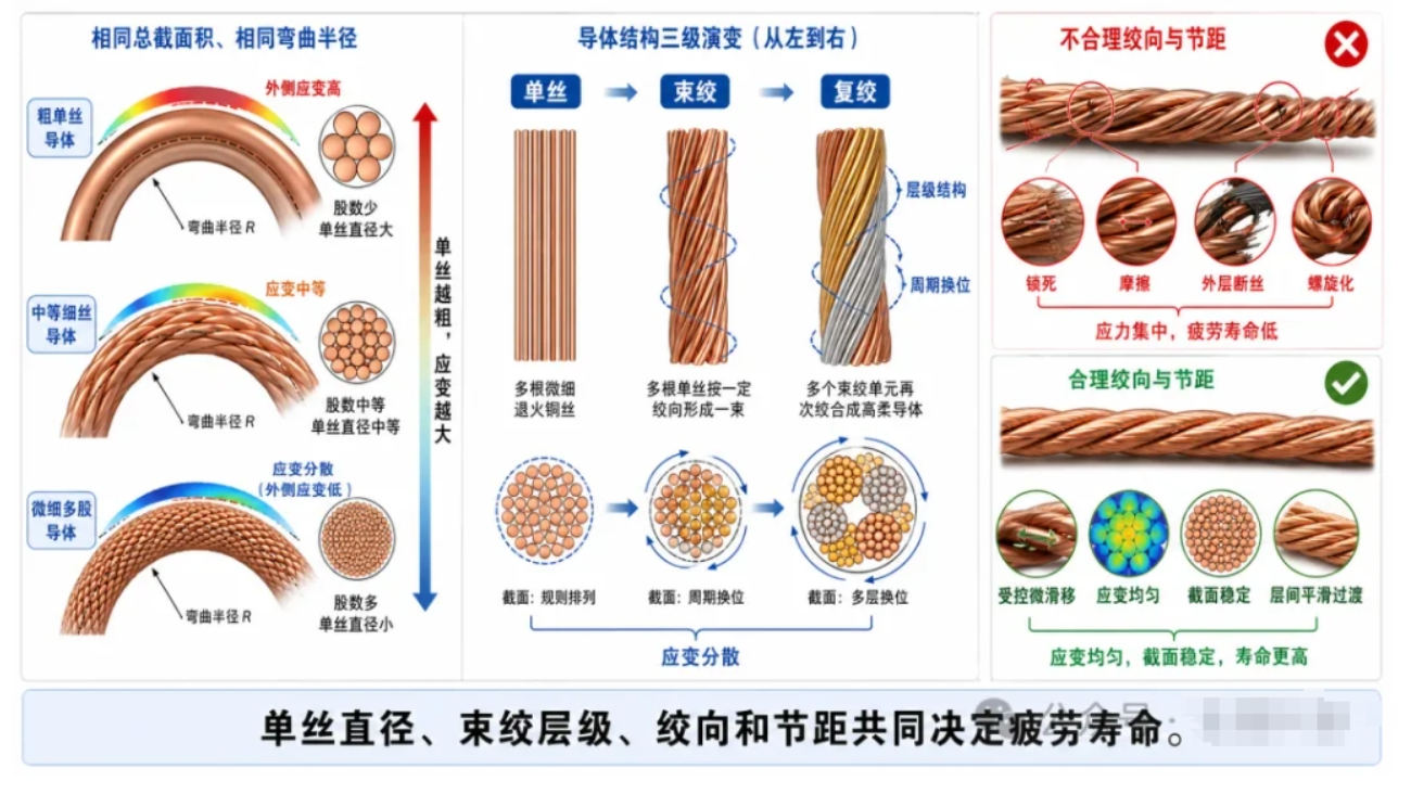
Figure 1 Structural Differences Between Ordinary Flexible Cables, Drag Chain Bending Cables, and Robot Torsion Cables
II. Why Are Fine Copper Wires More Resistant to Bending Than Thick Copper Wires?
Splitting a conductor with the same cross-sectional area into more and thinner individual strands is the most fundamental design approach for continuously moving cables. For a single round wire, under the same bending radius, surface axial strain is approximately proportional to wire diameter. The thinner the individual strand, the smaller the tensile and compressive strain generated during each bending cycle, and the greater the number of cycles usually required for cracks to initiate from surface defects and propagate.
This is also one of the reasons why IEC 60228 distinguishes flexible copper conductors from fixed-installation conductors. The standard specifies requirements for the cross-sectional area, resistance, and wire diameter of flexible copper conductors, but it is not equivalent to a “robot lifetime standard.” Meeting flexible conductor resistance requirements only indicates that the conductor has basic flexibility and electrical conductivity; it does not prove that it can withstand millions of robotic arm movements[8].
Fine stranding also provides two additional effects. First, multiple individual strands can undergo small relative movements, preventing the conductor from bending as a rigid copper rod. Second, if one individual strand is locally damaged, the remaining strands can temporarily maintain electrical continuity. Therefore, cables often first show slowly increasing resistance and intermittent open circuits before developing complete failure.
However, individual strands are not simply “the thinner the better.” Excessive numbers of strands increase contact area and internal friction, raising the costs of drawing, annealing, stranding, and termination. Extremely fine strands are more likely to be damaged during stripping, crimping, or soldering, and copper powder and oxidation are also more difficult to control. Product design must balance bending lifetime, conductor outer diameter, DC resistance, manufacturing cost, and termination reliability.
III. What Truly Creates the Lifetime Difference Is the Stranding Method, Not Just the Number of Strands
Two cables can have the same cross-sectional area and similar individual strand diameters, yet have completely different fatigue lives due to different stranding methods. Key variables include strand direction, lay length, stranding hierarchy, conductor roundness, compaction level, and whether different layers can maintain stable sliding.
Drag chain cables often use multi-level stranding: several fine wires are first combined into small bundles, and then these bundles are further stranded around the center. This allows the conductor to form multiple relatively independent small movement units during bending, preventing all individual strands from experiencing maximum tensile and compressive strain at the same location.
If the lay length is too long, the conductor may become loose, migrate, and experience local strain concentration during bending; if the lay length is too short, internal contact frequency increases, and during torsion the individual strands cannot release axial shear, which may create higher friction and a “tightening” effect. Robot torsion cables require longer lay lengths and torsional balance because the load from robotic arms is not simple bending, but repeated rotation of the entire cable around its own axis[4,9].
Compacted conductors are beneficial in ordinary power cables because they reduce outer diameter, but they may cause geometric indentations on individual strand surfaces and local stress concentration. Fatigue studies on stranded copper conductors show that irregular strand surfaces and cross-sections, wire-to-wire contact, and local bending stresses significantly affect fatigue initiation points[10-13]. Therefore, high-flex conductors usually do not simply pursue the highest filling factor, but instead reserve space for relative movement between individual strands.
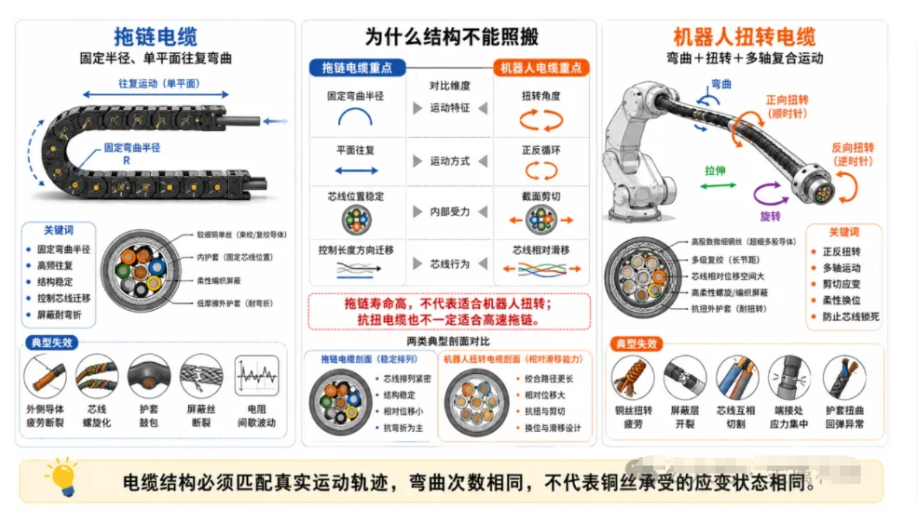
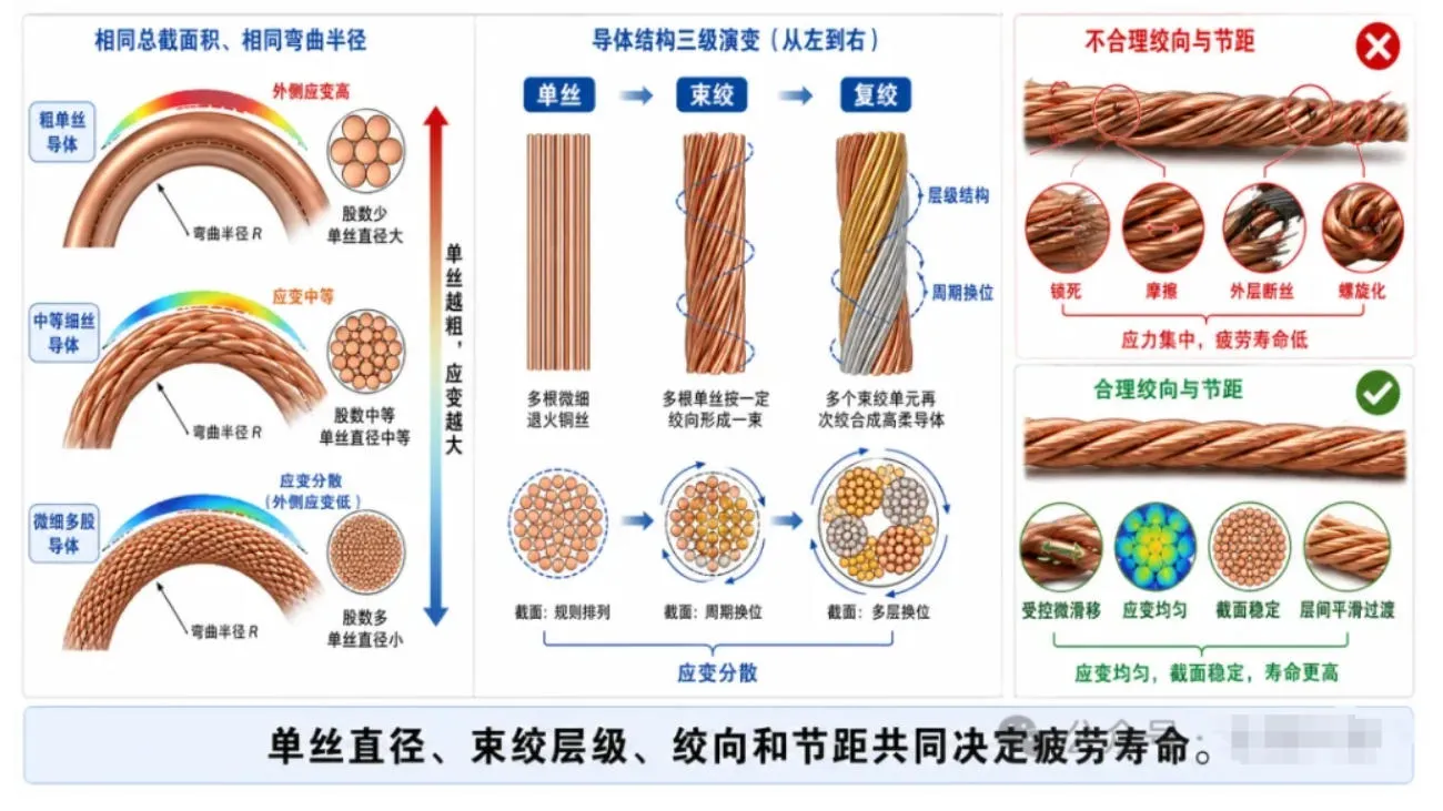
Figure 2 How Fine Strands, Stranding Lay Length, and the Neutral Axis Work Together to Reduce Copper Wire Fatigue
IV. Why Do Cables Always Break at the Same Location?
Breakage of robot cables usually shows obvious location patterns: both ends of drag chains, robot joint exits, areas near fixtures, locations where bending radius suddenly changes, and areas where stress relief at terminals is insufficient are the most dangerous. These areas are either subjected to the highest number of movements, have the largest strain gradients, or restrict the free movement of conductors inside the cable.
When a cable leaves a drag chain or protective tube, a stable “static zone” or transition area is required so that bending can gradually develop. If the static zone is too short, clamping is too tight, or the drag chain is overfilled, the core wires are forced to migrate and form spiral deformation, which is commonly known as corkscrewing. Alpha Wire’s failure guidelines identify insufficient static zones, excessive crowding, insufficient bending radius, incorrect selection, and installation twisting as important causes of early high-flex cable failure[14].
For copper conductors, local failure usually develops through the following path:
Individual strand surface scratches or drawing defects become crack initiation points; outer-layer strands first fracture under repeated tension and compression; load transfers to the remaining strands; wire-to-wire friction and fretting wear intensify; conductor resistance increases and local heating occurs; finally, intermittent open circuits or complete circuit interruption occur.
The contact between multiple copper strands can also generate fretting wear. Dynamic cable studies show that crossing contact, friction, and repeated sliding between copper wires can produce wear debris, surface pits, and fatigue cracks. Inter-wire load and friction coefficient have significant effects on lifetime[15-17]. Although these studies include submarine dynamic cables as research objects, their basic mechanism of “multi-strand copper wires + repeated bending + wire-to-wire contact” is also useful for understanding robot cables.
V. The Shielding Layer Is Actually a Second Fatigue Conductor System
Servo, encoder, industrial Ethernet, and vision system cables usually contain shielding. The shielding layer must maintain low-impedance return paths and electromagnetic shielding performance while also bending and twisting together with the cable. Therefore, it is itself a thinner and more fragile dynamic conductor system.
Ordinary aluminum-plastic composite foils provide high shielding coverage in static cables, but may crack under repeated bending. Traditional copper braided shields generate friction at crossing points and may locally tighten during torsion. Robot cables often use optimized braid angles, fine copper wire braids, spiral wrapping, or special copper tape structures, allowing the shield to undergo controlled displacement during torsion[5-7].
Lenz et al. conducted RF measurements on repeatedly bent coaxial cables and twisted-pair cables, finding that foil shield cracking and increased copper conductor surface roughness can cause changes in attenuation and phase response. This indicates that cables may experience communication performance degradation before complete circuit failure occurs[18]. Therefore, robot data cables cannot only undergo continuity testing; impedance, insertion loss, return loss, and shielding continuity should also be considered.
VI. The Jacket Is Not Unimportant, but a Soft Jacket Cannot Save an Incorrect Copper Wire Structure
Emphasizing copper wire structure does not mean denying the importance of jackets and insulation. The jacket determines abrasion resistance, oil resistance, flame retardancy, temperature range, and external friction; the core insulation and filler layers determine internal sliding, roundness, and interlayer pressure. If insulation materials have excessively high friction coefficients, individual strands and cores cannot redistribute their positions during bending, and even excellent copper conductors will experience additional stress.
A truly long-life cable must form an internal structure that is “flexible but not loose”: the cores can move slightly, but cannot migrate uncontrollably during long-term operation; fillers maintain roundness without compressing the cores excessively; the jacket restrains the overall structure while allowing internal layer-to-layer sliding.
Therefore, high-flex cables are not created by simply making all materials softer. An excessively soft jacket may cause sticking, wear, or core migration inside drag chains; an excessively hard jacket increases bending force and spring-back. Material hardness, wall thickness, internal pressure, and copper conductor stranding must be designed together.
VII. What Does “10 Million Cycles” Actually Represent?
The number of cycles must be linked to complete test conditions. At minimum, the following factors should be specified simultaneously:
· Whether it is bending, torsion, or a combination of both;
· The ratio between dynamic bending radius and cable outer diameter;
· Travel distance, speed, acceleration, and stopping method;
· Torsion angle, effective torsion length, and torsion direction;
· Environmental temperature, oil contamination, coolant, and wear conditions;
· Whether the cable is energized during testing, carries current, or transmits high-speed signals;
· Whether the failure criterion is open circuit, resistance drift, shielding attenuation, or jacket damage.
The cycle numbers from different manufacturers in the market cannot necessarily be compared directly. A product that passes 10 million cycles under a large bending radius, low speed, room temperature, and single-axis bending condition does not necessarily achieve the same lifetime under smaller radius, rapid emergency stops, oil mist, and axial torsion environments.
Currently, standards such as IEC 60228, UL 758, and UL 1581 can regulate conductor resistance, materials, and basic cable testing, while NFPA 79 can be used as an application and installation framework for industrial machinery electrical systems[8,19-22]. However, the composite motion lifetime of robot cables still often depends on specific product specifications and manufacturer tests. During procurement, test conditions close to the actual motion trajectory must be requested.
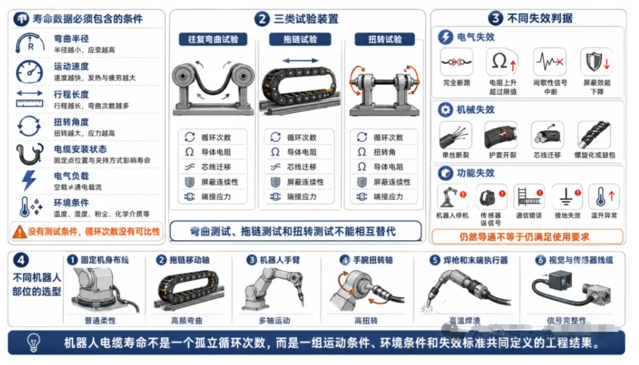
Figure 3 Failure Chain and Verification Loop of Robot Cable from Individual Strand Breakage to System Downtime
VIII. Different Robot Locations Have Different Cable Requirements
| Robot Location | Main Motion | Structural Focus | Verification Conditions That Must Be Defined |
|---|---|---|---|
| Drag chain axis / linear module | Reciprocating bending in a fixed plane | Fine stranded wires with short lay length, low-friction cores | Bending radius, travel distance, acceleration |
| Six-axis robot joints | Axial torsion and bending | Long lay length, torsion balance, special shielding | ± angle/m, effective torsion length |
| Hollow wrist and end tools | Complex motion in limited space | Small outer diameter, multiple cores/mixed cables, reinforced termination | Local stress, minimum radius, interface lifetime |
| Welding robots | Motion + welding spatter + high temperature | Welding-spatter-resistant jacket, coordinated shielding and conductor design | Thermal particles, oil contamination, emergency stops |
| Vision / encoder cables | Motion + high-speed signals | Stable impedance, fatigue-resistant shielding | Insertion loss, return loss, phase performance |
| Collaborative robots | Frequent posture changes and human-machine interaction | Lightweight, flexible, low reaction force | Combined bending and torsion, outer diameter and weight |
This is also why a “single high-flex cable for all robot applications” is usually unrealistic. Motor power cables, brake cables, encoder cables, industrial Ethernet cables, and air tubes may exist in the same harness, but their conductor cross-sections, shielding structures, and allowable strains are different. The overall harness layout must prevent the stiffest components from transferring stress to the most fragile signal cables.
IX. Cable Breakage Analysis Cannot Only Focus on the Fracture Point
When intermittent failures occur in robot cables, simply finding “where it broke” is not enough. The breakage location, motion phase, and electrical changes should be correlated.
| Symptom | More Likely Mechanism | Priority Inspection |
|---|---|---|
| Repeated conductor breakage at a fixed location | Local bending radius too small, clamping point, or sudden change in guidance | Check motion trajectory, clamps, and transition zones |
| Outer copper strands break first | Concentrated bending tensile/compressive strain, surface defects | Cross-sectional metallography, individual strand diameter and surface inspection |
| Copper powder and black wear debris | Inter-wire fretting wear or core friction | Check stranding, internal pressure, lubrication/isolation |
| Gradually increasing resistance | Partial strand breakage, contact degradation | Online four-wire resistance and temperature rise monitoring |
| Occasional communication packet loss | Shielding damage, impedance change, or conductor surface roughness | VNA, TDR, insertion loss/return loss testing |
| Cable spiraling | Incorrect selection, insufficient static zone, installation torsion | Check printing line, drag chain filling, and lay length |
| Breakage near terminals | Insufficient strain relief, sudden stiffness transition | Check termination structure and rear support |
When conditions allow, DC resistance, shielding impedance, or high-speed signal phase can be used as state variables for predictive maintenance. Research shows that RF phase changes caused by mechanical wear may indicate remaining lifetime earlier than amplitude changes[18]. For critical robotic production lines, such online monitoring is more valuable than blindly replacing cables according to fixed schedules.
X. When Purchasing Robot Cables, At Least These Ten Items Should Be Clearly Defined
·Motion type: drag chain bending, axial torsion, or composite motion;
·Dynamic minimum bending radius, not only static bending radius;
·Torsion angle, effective length, and cycles per minute;
·Travel distance, speed, acceleration, emergency stop frequency, and expected lifetime;
·Conductor cross-sectional area, individual strand structure, and DC resistance at 20 ℃;
·Number of cores, shielding method, and high-speed signal standards;
·Requirements for oil resistance, coolant resistance, welding spatter resistance, temperature range, and flame retardancy;
·Installation space, drag chain filling ratio, static zone, and clamping method;
·Termination method, connector rear strain relief, and replacement method;
·Cycle test conditions, failure criteria, and batch traceability.
If a supplier only provides labels such as “ultra-flexible,” “high bending resistance,” and “10 million cycles,” but does not specify bending radius, speed, torsion angle, and failure criteria, this lifetime value is difficult to apply in engineering design.
XI. Conclusion: True Bending Resistance Comes Not from a Soft Cable, but from a Structure That Can Distribute Strain
Robot cables can bend millions of times not because copper wires have no fatigue, but because designers divide one large deformation into countless small deformations distributed among individual strands, multiple stranding units, and multiple sliding interfaces. Fine strands reduce local strain, stranding and lay length determine how strain is distributed, insulation and fillers control internal friction, while shielding and jackets maintain the integrity of the entire structure in the environment.
This also explains why two cables with similar appearances may have lifetimes differing by an order of magnitude. The real differences are often hidden beneath the jacket: how fine the individual strands are, how they are bundled, how the lay length is configured, whether the cores can move, how shielding withstands torsion, and whether the termination suddenly interrupts movement.
Therefore, robot cable failure cannot simply be attributed to jacket cracking, nor can it be solved only by using softer materials. If the copper conductor structure does not match the movement mode, even the most wear-resistant jacket will only hide internal conductor breakage for a longer time.
The core capability of a robot cable is not being “extremely soft,” but continuously and controllably redistributing strain during millions of movements.
References and Standards
The following references are used to support discussions on flexible conductors, stranding fatigue, inter-wire fretting wear, shielding degradation, robot cable structures, and cycle verification. Manufacturer cycle lifetime data only applies to their publicly disclosed test conditions and should not be directly compared across products without considering bending radius, speed, and torsion angle.
[1] IEC. IEC 60228:2023, Conductors of insulated cables.
[2] UL Solutions. ANSI/UL 758, Appliance Wiring Material; Appliance Wiring Material Testing and Certification Services.
[3] UL Standards. UL 1581, Reference Standard for Electrical Wires, Cables, and Flexible Cords.
[4] NFPA. NFPA 79, Electrical Standard for Industrial Machinery, 2024 edition and 2027 revision documents.
[5] LAPP. The Next Generation of Advanced Robotics. Technical White Paper.
[6] LAPP. ÖLFLEX ROBOT F1 and ÖLFLEX ROBOT 900 DP product data: torsion ratings and cycle testing.
[7] igus. chainflex Robot Cables and Robotics Solutions technical data.
[8] igus. 7 Guidelines for Continuous-Flex Cables. Technical Guide.
[9] Alpha Wire. 7 Common Causes of Premature High-Flex Cable Failure. White Paper, 2021.
[10] SAB Bröckskes. Selecting and Installing Continuous Flex Cable: Frequently Asked Questions.
[11] Proterial. Industrial Robot Cable product information.
[12] TPC Wire & Cable. Flexing Wire and Cable Applications technical guide.
[13] Liang W, Guan W, Ding Y, Hang C, Zhou Y, Zou X, Yue S. Mechanical Properties and Fatigue Life Analysis of Motion Cables in Sensors under Cyclic Loading. Sensors, 2024, 24: 1109. doi:10.3390/s24041109.
[14] Nasution F P, Saevik S, Gjoesteen J K O, Berge S. Experimental and finite element analysis of fatigue performance of copper power conductors. International Journal of Fatigue, 2013. doi:10.1016/j.ijfatigue.2012.09.006.
[15] Nasution F P, Saevik S, Gjoesteen J K O. Finite element analysis of the fatigue strength of copper power conductors exposed to tension and bending loads. International Journal of Fatigue, 2014, 59: 114-128. doi:10.1016/j.ijfatigue.2013.09.009.
[16] Nasution F P, Saevik S, Berge S. Experimental and finite element analysis of fatigue strength for 300 mm2 copper power conductor. Marine Structures, 2014. doi:10.1016/j.marstruc.2014.07.005.
[17] Poon C, O’Halloran S M, Connolly A, Barrett R A, Leen S B. Fretting wear and fatigue in submarine power cable conductors for floating offshore wind energy. Tribology International, 2023, 186: 108598. doi:10.1016/j.triboint.2023.108598.
[18] Poon C, O’Halloran S M, Barrett R A, Leen S B. Three-dimensional representative modelling for fretting wear and fatigue of crossed copper conductors. International Journal of Fatigue, 2024.
[19] Lenz P, et al. Wear-Induced Attenuation on Transmission Lines and Their Causes. Transactions on Electrical and Electronic Materials, 2023. doi:10.1007/s42341-022-00423-7.
[20] Xie Y, Lei J, Hua F, Hu J, Liu D, He Y. Size and passivation effects in the torsion of thin metallic wires. Acta Mechanica Sinica, 2023, 39: 422346. doi:10.1007/s10409-022-22346-x.
[21] Guo S, He Y, Tian M, Liu D, Li Z, Lei J, Han S. Size effect in cyclic torsion of micron-scale polycrystalline copper wires. Materials Science and Engineering A, 2020, 792: 139671.
[22] Liu D, He Y, Tang X, Ding H, Hu P, Cao P. Size effects in the torsion of microscale copper wires: Experiment and analysis. Scripta Materialia, 2012, 66: 406-409.
[23] Kuznecovs A, et al. A methodology for design and fatigue analysis of power cables for dynamic applications. International Journal of Fatigue, 2019.
[24] Poon C, et al. Fretting wear and fatigue life for dynamic power cable conductors. Reliability Engineering & System Safety, 2025.
[25] IEC. IEC 61156-1:2023, Multicore and symmetrical pair/quad cables for digital communications – Generic specification.
[26] IEC. IEC 60332-1-2:2025, Test for vertical flame propagation for a single insulated wire or cable.
[27] IEC. IEC 60227-5:2024, Polyvinyl chloride insulated flexible cables (cords).
[28] Northwire. The Engineer’s Guide to Custom Cable Design. White Paper.
[29] LAPP. Cables and wires for robots and torsion: application and product guidance.
[30] igus. Robotic Cable Failures: Flexibility, Pitch Length and Torsion. Technical Article.
-
Tel:
-
E-mail:
-
Address:
No.1 Chengxi West Road, Cicheng, Ningbo, China
-

Ms.Yu
-

Ms.Sun