
 中文
中文

Are Thinner Copper Wires in Robot Cables More Bend-Resistant?
In promotional materials for robot cables, keywords such as “0.05 mm ultra-fine copper wire,” “millions of bending cycles,” and “high-flexibility stranded conductors” are often seen. Over time, it is easy for people to form a seemingly reasonable judgment: as long as the copper wires are made fine enough, the cable will certainly be more flexible, more resistant to bending, and its service life will naturally increase.
This judgment is only half right. For a single copper wire, reducing the wire diameter can indeed reduce the surface strain under the same bending radius and significantly reduce bending stiffness. However, a robot cable is not an ideal bundle of independent fine wires that never rub against one another. It is a multilayer mechanical system composed of dozens, hundreds, or even thousands of copper wires, insulation layers, fillers, shielding layers, jackets, and termination structures. Whether the copper wires can survive “millions of cycles” depends not only on wire diameter, but also on lay length, lay direction, strand structure, material condition, internal friction, bending radius, torsion angle, end constraints, and test criteria.[1-10]
Therefore, the real question is not “whether the finer the copper wire, the better,” but rather: under given current, space, motion trajectory, and lifetime targets, how can each copper wire be made to withstand smaller, more uniform, and repeatable cyclic strain, while preventing local contact and end structures from concentrating stress again?
I. Why are fine copper wires usually more resistant to bending? Start with the simplest geometric relationship
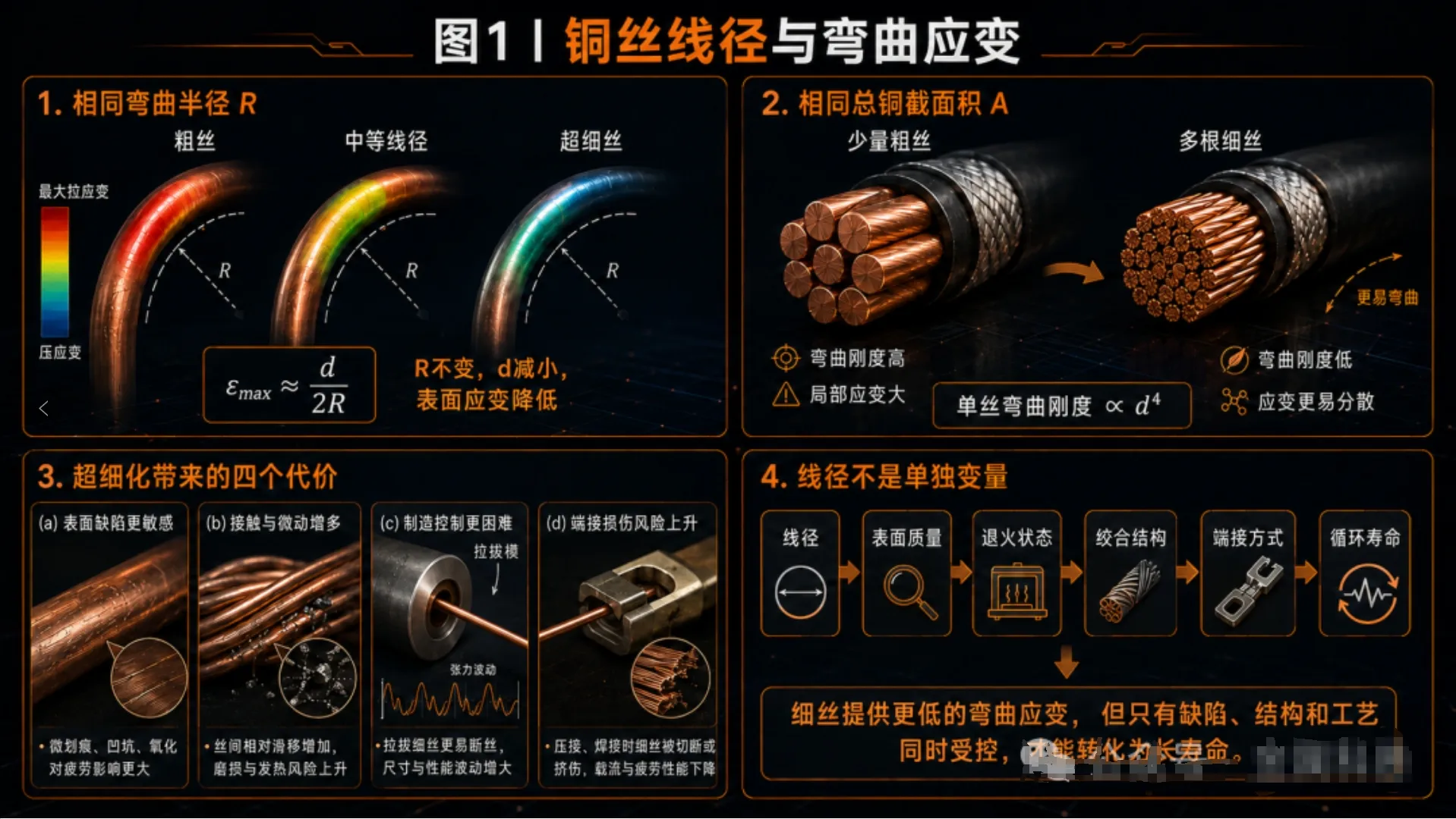
If a round copper wire with a diameter of d is bent into an arc with a curvature radius of R, under the small-deformation approximation, the bending strain on the outermost surface of the copper wire can be written as:
εmax ≈ d / (2R)
This means that when the bending radius remains unchanged, if the diameter of a single wire is halved, the geometric bending strain on the outermost layer is also approximately halved. At the same time, the area moment of inertia of a round wire is proportional to the fourth power of its diameter, so the bending stiffness EI of a single copper wire decreases rapidly with d⁴. Therefore, dividing the same total copper cross-sectional area into more and finer individual wires can usually make the conductor easier to bend and can also reduce the cyclic strain borne by each individual wire under the same curvature.
From this perspective, “fine wires are more resistant to bending” is not a marketing concept, but has a clear mechanical basis. IEC 60228 classifies flexible copper conductors into Class 5 and the more flexible Class 6; ASTM B738 specifically covers fine-wire bunch-stranded and rope-lay copper conductors with diameters below 0.078 mm, indicating that ultra-fine individual wires and multi-stage stranding are themselves mature engineering approaches.[1,6]
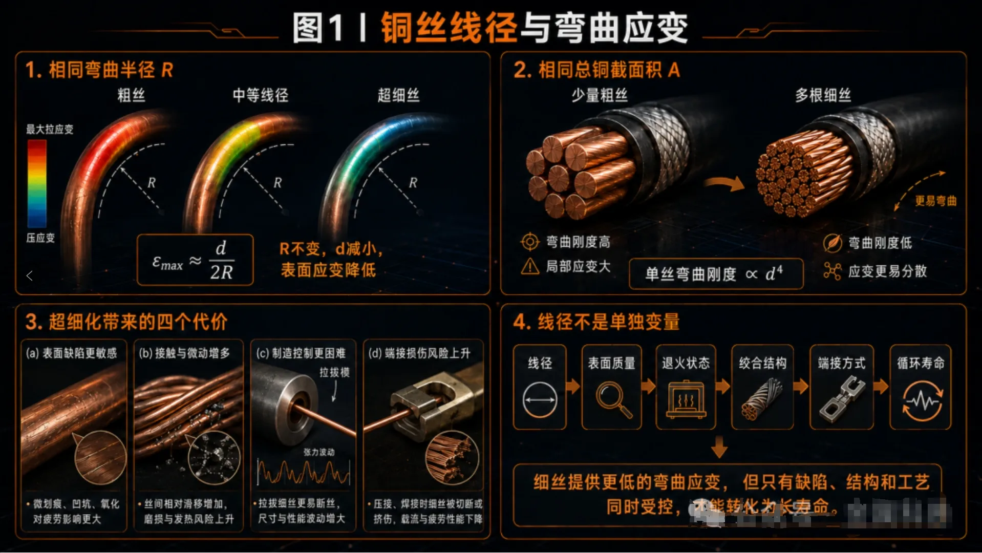
However, there is an easily overlooked premise here: the above derivation is for an ideal single wire. The bending stiffness of a real stranded conductor lies between two limits—if the individual copper wires can slide freely, the conductor is close to “many independent fine wires”; if the copper wires are compacted, bonded, or firmly locked by the insulation layer, the entire conductor bundle behaves more like a thick solid rod. In other words, wire diameter determines potential flexibility, while structure determines whether that flexibility can truly be released.

II. The finer the copper wire, the more bend-resistant it tends to be, but it cannot be infinitely fine: four costs gradually emerge
1. Surface area increases rapidly, making surface quality more important
When the total copper cross-sectional area remains unchanged, the finer the individual wires, the larger the total surface area. The effects of drawing die marks, scratches, exposed inclusions, local oxidation, and discontinuous plating on fatigue life will also be amplified. Fatigue cracks in copper wires usually initiate from surface or near-surface defects. Tests and finite element studies on stranded copper conductors have found that compaction and manufacturing-induced geometric irregularities can cause additional local bending, and the stress peaks and fracture locations do not necessarily correspond to the nominal load.[11-15]
Therefore, ultra-fine wire production is not simply a matter of “making the die hole smaller.” It requires cleaner and more stable copper rod, more uniform microstructure, stricter drawing lubrication and die management, and more precise online tension control. Research by Tokutomi et al. on the continuous bending-drawing process of fine copper alloy wires shows that the manufacturing path changes cross-sectional hardness, residual strain, and microstructure. This means that even with the same composition and wire diameter, completely different fatigue scatter may result from different processing histories.[20,21]
2. Single-wire strength, elongation, and annealing condition must be rebalanced
Hard-drawn copper wire has higher strength, but it often retains more work hardening and residual stress. Full annealing can reduce strength and improve elongation and flexibility, but excessive softening may also make local flattening and plastic deformation more likely during stranding, extrusion, and termination. ASTM B3 specifies requirements for tensile strength, elongation, and resistivity of soft copper wire, but these static indicators can only describe the basic material condition and cannot be directly equated with dynamic bending life.[2]
Fatigue studies on fine wires also show that grain size, annealing condition, loading mode, and test frequency all affect lifetime curves; fatigue data for copper wire itself has substantial statistical scatter.[24,25] Therefore, high elongation is usually beneficial, but “the highest elongation” does not automatically mean “the longest million-cycle life.” What is truly needed in engineering is low defects, low residual stress, stable cyclic plastic response, and batch-to-batch consistency.
3. Contact interfaces increase, and fretting wear and internal friction may rise
After a thick wire is divided into hundreds of fine wires, the contact points and contact lines between copper wires increase significantly. During bending, strands undergo relative sliding, squeezing, and fretting. An appropriate amount of sliding can release bending strain, but excessive contact pressure, surface roughness, or repeated micro-slip can cause wear, indentations, local work hardening, and fretting fatigue. Studies on multi-strand copper conductors have identified contact friction, local slip, and wear as important mechanisms affecting fatigue life.[12-17]
This is also why “more strands” cannot always be linearly converted into longer life. If stranding is too tight, the degree of compaction is too high, strand surfaces are rough, or insulation extrusion pressure prevents the strands from moving in a coordinated way, the geometric advantages of ultra-fine wires will be offset by internal friction and local contact stress.
4. Manufacturing, inspection, and termination become more difficult at the same time
Ultra-fine wires are more prone to breakage during drawing, stranding, pay-off, and stripping, and local damage is harder to detect through ordinary visual inspection. During termination, fine wires may splay, be cut, be crimped unevenly, or experience solder wicking. As long as some strands near the terminal are fixed first, the remaining freely bendable length is shortened, and bending strain concentrates at the rigid-flexible transition zone. As a result, the copper wires themselves may have no problem, yet the cable may fail first at the terminal, jacket exit, or beside a fixing clamp.
III.The second variable that truly determines life: not “how many wires,” but “how they are stranded”
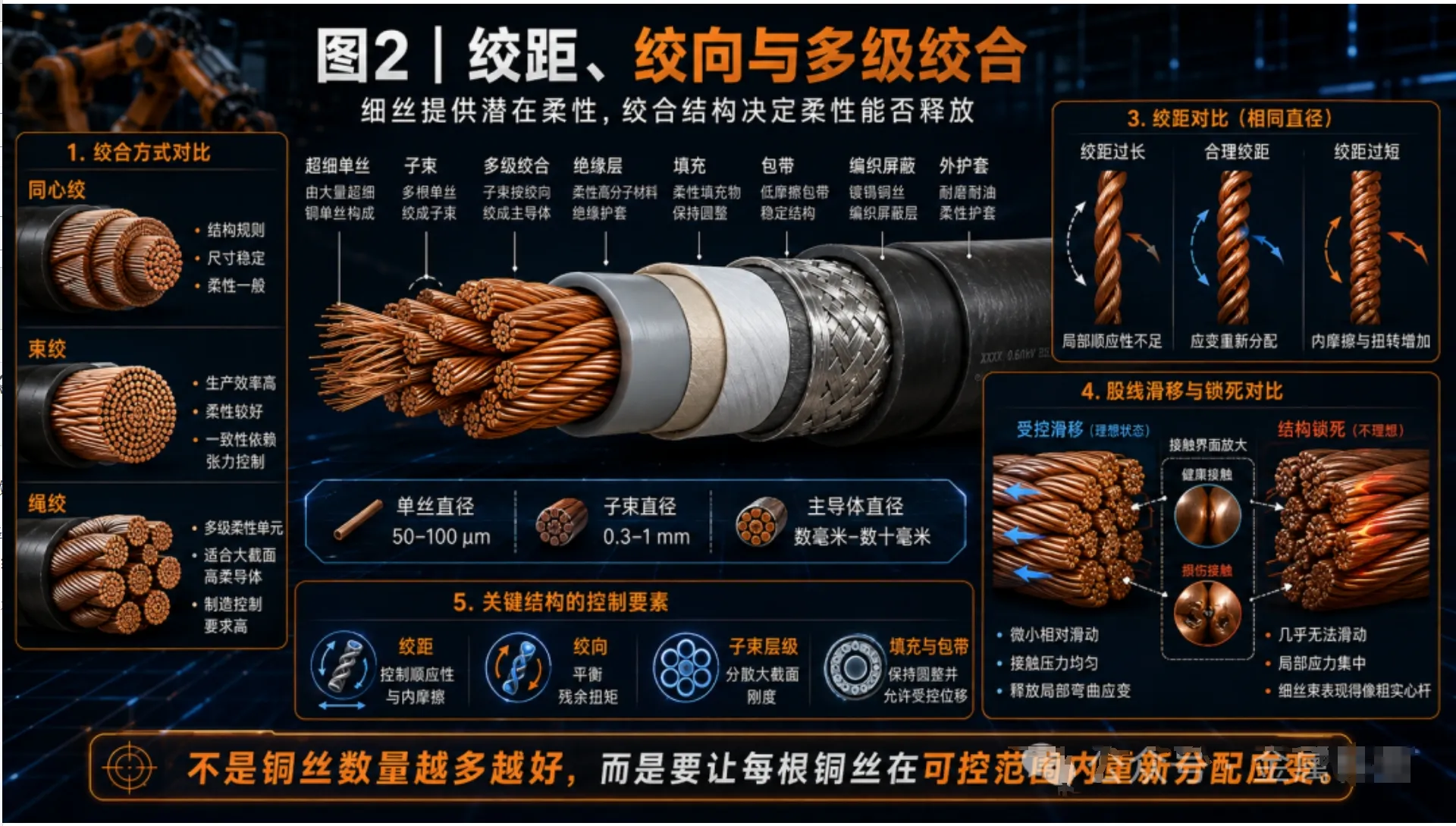
ASTM distinguishes copper conductors into different structures such as concentric-lay, bunch-stranded, and rope-lay. In general, concentric-lay structures are regular and dimensionally stable, making them suitable for ordinary power and control cables. Bunch stranding gathers multiple fine wires in one step, offering high production efficiency and good flexibility. Rope-lay stranding first forms fine wires into sub-bundles and then strands multiple sub-bundles in a second or multiple stages, allowing large-cross-section conductors to achieve higher flexibility.[3-6]
For robot cables, the stranding structure must address at least four issues at the same time:
·Lay length: A shorter lay length usually improves geometric compliance, but it also increases the actual copper wire length per unit cable length, helix angle, number of contacts, and torsion coupling. A longer lay length results in a smaller resistance increase, but may cause the conductor to behave more like a single body during local bending. The optimal lay length should be determined through motion mode analysis and testing, rather than simply pursuing “the shorter, the more flexible.”
·Lay direction: A reasonable combination of lay directions in adjacent layers can balance residual torque and structural rotation tendencies. If lay direction is designed improperly, repeated motion may cause strand migration, conductor bulging, or “spiraling” of the entire cable.
·Sub-bundle structure: Rope-lay conductors use multi-stage structures to divide a large cross-section into multiple flexible units that can move relative to one another, which helps reduce local stiffness. However, the more levels there are, the higher the requirements for tension consistency, roundness, and filling structure.
·Filling and wrapping tape: Fillers and wrapping tapes need to maintain the roundness of the cable core while allowing each core to undergo controlled displacement during bending. If too loose, they may cause impact, wear, and core shifting; if too tight, they may lock the entire cable into a rigid composite rod.
Therefore, bend-resistance design for robot cables is not a “competition in the number of fine wires,” but an integrated optimization of individual wire diameter, strand count, lay length, lay direction, hierarchy, and constraints.

IV.Robot cables do not face one type of bending, but three completely different types of motion
Many products claim “millions of bending cycles,” but if the motion method is not specified, this number has almost no comparability. In testing robot and continuous-motion cables, UL distinguishes different test processes such as reciprocating bending, drag-chain motion, torsion, and comprehensive flexing.[7,8] For robot cables, at least the following three operating conditions must be distinguished:
1. Drag-chain reciprocating bending: the bending radius is relatively stable, but the number of cycles is high
Cables in drag chains usually move reciprocally in an approximately fixed plane, with the bending zone moving along with the drag chain. The main variables include cable outer diameter D, minimum bending radius R, stroke, speed, acceleration, space inside the drag chain, and mutual friction between cables. In this case, an excessively small R/D directly increases the bending strain of copper wires; if the cable is packed too tightly or cannot move freely, local curvature may also become uncontrolled.
2. Robot wrist torsion: the dominant load is repeated rotation along the axis
Six-axis robots, especially wrist cables, often withstand reciprocating torsion described by the “torsion angle per meter.” The individual wires are not simply bent into arcs, but are subjected to helical stretching, shear, and strand rearrangement. At this point, finer individual wires are still beneficial, but lay-direction balance, cable-core symmetry, shielding structure, and jacket rebound capability are often more critical than simply reducing wire diameter.
3. Combined bending and torsion: the most dangerous in reality and the hardest to reproduce with a single test
The actual trajectories of robot joints often include bending, torsion, tension, acceleration shocks, and posture changes at the same time. Yoon et al. predicted the fatigue life of industrial robot cable harnesses through dynamic simulation, indicating that life should be based on the strain history generated by real motion trajectories. Chen et al., in their study of vibration-induced harness failure, observed that the first bending mode of a harness can trigger wire fretting, causing resistance to rise rapidly in the late stage of life.[9,10]
Therefore, a reciprocating bending test passed by a drag-chain cable cannot directly prove that it is suitable for robot wrist torsion. Likewise, a cable that reaches five million cycles at room temperature and low speed cannot be directly assumed to have the same life under high acceleration, oil contamination, or low-temperature environments.
V.Why do many cables fail not in the middle, but at the terminal and jacket exit?
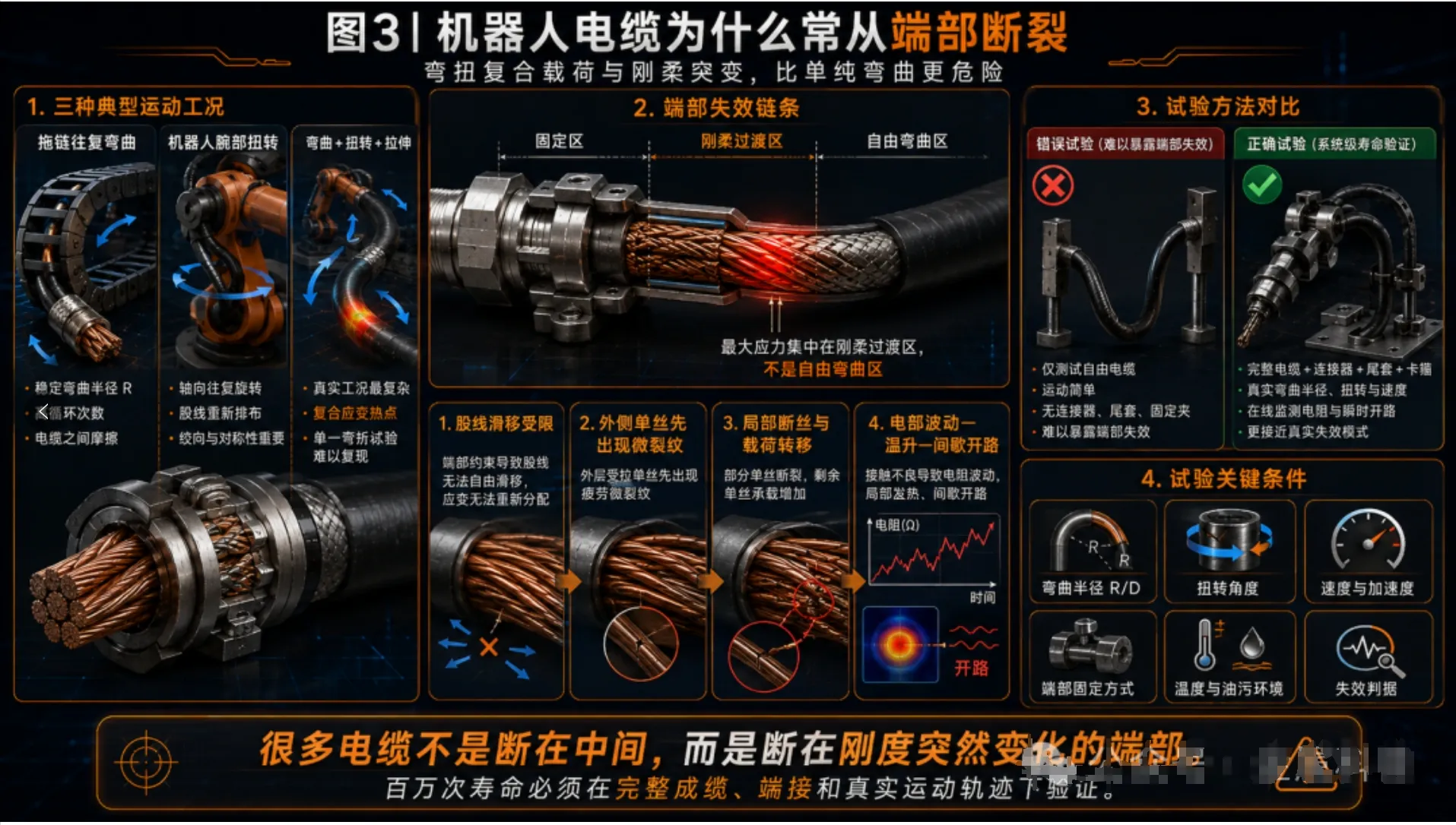
Ideally, the bending of a robot cable should be distributed over a sufficiently long active section. However, in real assemblies, connectors, crimp terminals, potting compound, heat-shrink tubing, cable ties, clamps, and jacket stripping openings can abruptly change local stiffness. The position where the cable transitions from “almost completely fixed” to “free to move” forms a typical rigid-flexible discontinuity.
In this transition zone, the common failure chain is:
·The terminal or potted section restricts strand sliding, forcing bending to concentrate within a range of a few millimeters to several tens of millimeters at the end;
·The outer strands first bear greater tensile strain, and individual wires near the terminal develop local work hardening and microcracks;
·After some strands break, current and mechanical loads transfer to the remaining strands, causing local temperature rise and stress to continue increasing;
·Resistance may not change much in the early stage, until the proportion of broken wires reaches a certain critical value, at which point intermittent open circuits or rapid failure occur.
This shows that “stress relief” is not completed simply by adding a section of heat-shrink tubing at the end. A reasonable boot and overmolding structure should allow stiffness to change gradually along the length, control where the cable first enters the bending zone, and prevent clamp edges, jacket cuts, and crimp wings from becoming new stress concentration points. For robot harnesses, the termination structure and routing design are often just as important as the conductor itself.
VI.Copper grade and purity matter, but “high-purity copper” is not a universal answer to bending life
Robot cables usually prioritize soft high-conductivity copper or surface-plated soft copper fine wires, because they combine low resistance, good ductility, and a mature processing system. However, high purity only solves part of the impurity and conductivity problem; it does not automatically eliminate surface defects, residual stress, non-uniform grain size, drawing scratches, or stranding indentations.
Fatigue studies on copper conductors have repeatedly shown that local geometric defects and the actual stress state play a decisive role in service life. Nasution et al. found in 95 mm² and 300 mm² stranded copper conductors that local bending stress, contact friction, and manufacturing irregularities of individual wires can control the fatigue strength of the entire conductor. Viespoli et al. further pointed out that periodic indentations formed during conductor compaction simultaneously change local strain distribution, work-hardening state, and fatigue performance.[11-15]
For ultra-fine wires used in robots, material design is better guided by the combined goal of “sufficiently high conductivity + stable ductility + controllable manufacturing defects + reasonable cyclic strength.” If alloying elements are added to increase individual wire strength, conductivity, annealing window, drawability, and bending fatigue must be evaluated at the same time. If the pursuit is only extremely soft pure copper, damage during manufacturing and termination must also be prevented. The material is not better simply because it is purer; it must be stabilized together with structure and process.
VII.What are the key variables that determine million-cycle life?
When the life of a robot cable is broken down, at least seven groups of variables can be seen acting together. Wire diameter is only one of them.
| Variable | Usually favorable direction | Possible cost | Indicators that must be verified |
| Individual wire diameter | Reduce wire diameter to lower individual-wire bending strain and stiffness | Surface area increases, making manufacturing defects and wire breakage harder to control | Wire diameter distribution, surface defects, bending life |
| Strand count and stranding hierarchy | Increase strand count and use bunch stranding or rope-lay stranding to release strain | Contact interfaces, friction, and production complexity increase | Structural stability, roundness, local indentations |
| Lay length and lay direction | Optimize among flexibility, torque balance, and dimensional stability | Too short increases torsion coupling and contact; too long reduces compliance | Torque, spiraling, strand migration |
| Bending radius R/D | Increase bending radius | Takes up more space and limits robot routing | Minimum radius and curvature peaks in the real route |
| Torsion angle and effective length | Reduce torsion angle per unit length and increase effective active length | Routing space and path management become more complex | Angle/meter, torsion-zone length, combined motion |
| Copper wire condition | Low defects, moderate annealing, stable ductility | Too hard leads to fatigue; too soft is prone to indentation and deformation | Strength, elongation, cyclic response, batch scatter |
| Termination and stress relief | Gradual stiffness transition, with fixing points kept away from the active bending zone | Longer structure and higher assembly cost | End bending location, broken wires after crimping, pull-out force |
| Insulation and jacket | Low friction, wear resistance, and maintaining controlled movement of the cable core | Materials that are too soft may creep; materials that are too hard may lock the cable core | Coefficient of friction, low-temperature flexibility, wear and cracking |
VIII.Why can “millions of bending cycles” not be compared independently of test conditions?
Fatigue life is not a material constant, but the result of the combined effects of load, structure, environment, and failure criteria. For the same cable, changing the bending radius from 10D to 7.5D, doubling the speed, adding axial tension, or introducing torsion may all change the life by orders of magnitude. Fatigue data for copper wire itself also has significant scatter; Harlow’s statistical analysis of historical fatigue data for annealed copper wire emphasizes the importance of long-life prediction and confidence intervals.[25]
Therefore, when seeing “5 million cycles” or “10 million cycles,” at least the following conditions should be asked:
1. Is the test a drag-chain test, reciprocating swing test, roller bending test, or torsion test? Does it include combined bending and torsion?
2. What is the minimum bending radius? What is the R/D calculated based on the cable outer diameter D?
3. How are stroke, speed, acceleration, cycle frequency, and motion pauses set?
4. Is the sample a bare wire, a single-core wire, a complete cable, or an assembly with connectors and stress-relief structures?
5. What are the test temperature, humidity, oil contamination, low-temperature conditions, or other environmental conditions?
6. Does the cable bear additional tension, clamping force, and mutual friction inside the drag chain or robot body?
7. Is “failure” defined as complete open circuit, or as resistance increase, intermittent open circuit, broken-wire ratio, shielding attenuation, or jacket cracking?
Only when these conditions are consistent do cycle counts have comparative meaning. UL is able to perform tick-tock, drag-chain, torsion, and flexing tests on robot cables precisely because different motion modes correspond to different failure mechanisms.[7,8] For corporate procurement, a “million-cycle certificate” without complete test conditions has far less informational value than a reproducible set of operating conditions and failure criteria.
IX.How should companies design a truly meaningful robot cable lifetime test?
The first step is not to buy a bending tester, but to convert the robot’s real operating conditions into a load spectrum. It is recommended to establish the verification chain in the following order:
8. Motion definition: Extract joint angles, speeds, accelerations, pauses, and cycle times from the robot program, and identify the combination of bending, torsion, and tension.
9. Route reproduction: Install the sample according to the actual routing length, fixing points, bending radius, boot, and connector conditions, instead of testing only a free section of bare cable.
10. Layered samples: Test individual wires, stranded conductors, single-core insulated wires, complete cables, and terminated assemblies at the same time to distinguish material problems, structural problems, and assembly problems.
11. Online monitoring: Continuously or at high frequency collect conductor resistance, transient open circuits, insulation resistance, and signal quality. For high-speed communication lines, impedance and shielding performance should also be monitored.
12. Stage-by-stage dissection: At 10%, 30%, 60%, and 100% of the target life, take samples for sectioning and count broken-wire locations, strand wear, insulation indentations, and shielding damage.
13. Environmental coupling: Repeat key tests under target high/low temperature, oil contamination, damp heat, or dust conditions to prevent room-temperature results from masking material hardening, friction changes, and jacket cracking.
14. Statistical design: Set a sufficient sample size under the same conditions and record the life distribution, rather than displaying only “the best sample.”
Research on multi-strand copper conductors shows that whole-cable testing, single-wire fatigue data, and local contact models need to be calibrated against one another. Relying only on single-wire S-N curves is insufficient to cover local bending, indentations, and fretting wear in stranded structures.[11-19] For robot cables, the ultimate goal of testing is not to obtain an attractive cycle count, but to identify the first location of failure and prove that the design can be stably reproduced under the target operating conditions.

X. From the perspective of industry-academia-research collaboration, what is truly worth studying in robot cables?
For researchers, the easiest work is to compare the static tensile properties and single bending life of copper wires with different diameters. Research with real industrial value, however, should connect materials, structures, motion, and failure evidence. It is recommended to focus on:
·Establishing quantitative relationships among surface defects, grain condition, residual stress, and cyclic life of ultra-fine copper wires;
·Studying strand sliding, contact pressure, and local strain distribution under different lay lengths, lay directions, and multi-stage rope-lay structures;
·Developing life models under combined bending-torsion-tension loads, rather than treating the three types of loads independently;
·Identifying early wire breakage through resistance noise, acoustic emission, or online signal monitoring, and establishing a mapping from local damage to functional failure;
·Incorporating termination, boots, clamps, and whole-machine routing into the design to achieve cross-scale verification from “wire material—cable—assembly—robot.”
For industry, the most important thing is not to find the supplier with the “finest copper wire,” but to establish a traceable quality chain: whether copper rod cleanliness and oxygen content are stable, whether drawing dies and lubrication are controlled, whether intermediate annealing is uniform, whether stranding tension is consistent, whether insulation extrusion damages the conductor, whether the termination process cuts fine wires, and whether the final lifetime test reproduces the customer’s real motion. Million-cycle life is not created by any single raw material alone, but is the result of the entire manufacturing chain holding the line together.
XI. Conclusion: Wire diameter determines the starting point; structure and system determine the endpoint
Making copper wires finer can indeed reduce individual-wire bending strain and bending stiffness, which is the basis for robot cables to achieve high flexibility and long life. However, once the wire diameter enters the ultra-fine range, manufacturing defects, annealing consistency, strand friction, lay-length design, insulation constraints, and end stress concentration become increasingly important. Focusing only on “0.05 mm” or “thousands of strands” is like judging a vehicle’s performance only by engine displacement: it is an important parameter, but not the complete answer.
What truly supports million-cycle life is a complete logic: use finer individual wires to reduce local strain; use reasonable stranding to allow controlled strand sliding; use materials and processes to reduce crack initiation sites; use jackets and fillers to stabilize motion patterns; use end structures to eliminate stiffness discontinuities; and finally verify the design through bending, torsion, and environmental tests consistent with real robot trajectories.
Therefore, the core of robot cables is not “the finer the copper wire, the better,” but ensuring that every copper wire deforms in the right place and in the right way.
References and Standards
[1] International Electrotechnical Commission. IEC 60228:2023, Conductors of Insulated Cables. Geneva: IEC, 2023.
[2] ASTM International. ASTM B3-13(2024), Standard Specification for Soft or Annealed Copper Wire. West Conshohocken, PA, 2024.
[3] ASTM International. ASTM B8-23, Standard Specification for Concentric-Lay-Stranded Copper Conductors, Hard, Medium-Hard, or Soft. West Conshohocken, PA, 2023.
[4] ASTM International. ASTM B172-17(2024), Standard Specification for Rope-Lay-Stranded Copper Conductors Having Bunch-Stranded Members, for Electrical Conductors. West Conshohocken, PA, 2024.
[5] ASTM International. ASTM B174-17(2024), Standard Specification for Bunch-Stranded Copper Conductors for Electrical Conductors. West Conshohocken, PA, 2024.
[6] ASTM International. ASTM B738-13(2018), Standard Specification for Fine-Wire Bunch-Stranded and Rope-Lay Bunch-Stranded Copper Conductors for Use as Electrical Conductors. West Conshohocken, PA, 2018.
[7] UL Solutions. UL Announces Capability for Performing Tests on Cables Used in Repeated Flexing Applications. 2019.
[8] UL Solutions. Robotic Cable: Tick-Tock, Torsion, Chain Track and Flexing Test Process Verified. UL Verification 272.
[9] Yoon, J. W.; Park, T. W.; Yim, H. J. Fatigue Life Prediction of a Cable Harness in an Industrial Robot Using Dynamic Simulation. Journal of Mechanical Science and Technology, 2008, 22: 484-489. DOI: 10.1007/s12206-007-1209-0.
[10] Chen, Y.; Chaudhry, Z.; Luker, W.; Zajac, M. Investigation of the Vibration Induced Harness Failure. Annual Conference of the PHM Society, 2022, 14(1). DOI: 10.36001/phmconf.2022.v14i1.3245.
[11] Nasution, F. P.; Sævik, S.; Gjøsteen, J. K. Ø. Fatigue Analysis of Copper Conductor for Offshore Wind Turbines by Experimental and FE Method. Energy Procedia, 2012, 24: 271-280. DOI: 10.1016/j.egypro.2012.06.109.
[12] Nasution, F. P.; Sævik, S.; Gjøsteen, J. K. Ø. Experimental and Finite Element Analysis of Fatigue Performance of Copper Power Conductors. International Journal of Fatigue, 2013, 47: 244-258. DOI: 10.1016/j.ijfatigue.2012.09.006.
[13] Nasution, F. P.; Sævik, S.; Gjøsteen, J. K. Ø. Finite Element Analysis of the Fatigue Strength of Copper Power Conductors Exposed to Tension and Bending Loads. International Journal of Fatigue, 2014, 59: 114-128. DOI: 10.1016/j.ijfatigue.2013.09.009.
[14] Nasution, F. P.; Sævik, S.; Berge, S. Experimental and Finite Element Analysis of Fatigue Strength for 300 mm² Copper Power Conductor. Marine Structures, 2014, 39: 225-254. DOI: 10.1016/j.marstruc.2014.07.005.
[15] Viespoli, L. M.; Johanson, A.; Dumoulin, S.; Hagen, A. B.; Wan, D.; Berto, F.; Alvaro, A. Impact of Conductor Assembly Indentation on the Fatigue Properties of Copper Power Cable Wires. Procedia Structural Integrity, 2022, 42: 1336-1343. DOI: 10.1016/j.prostr.2022.12.170.
[16] Poon, C.; O’Halloran, S. M.; Connolly, A.; Barrett, R. A.; Leen, S. B. Fretting Wear and Fatigue in Submarine Power Cable Conductors for Floating Offshore Wind Energy. Tribology International, 2023, 186: 108598. DOI: 10.1016/j.triboint.2023.108598.
[17] Poon, C.; Mhurchadha, S. U.; Barrett, R. A.; Leen, S. B. Three-Dimensional Representative Modelling for Fretting Wear and Fatigue of Submarine Power Cable Conductors. International Journal of Fatigue, 2024, 184: 108302. DOI: 10.1016/j.ijfatigue.2024.108302.
[18] Ringsberg, J. W.; et al. Characterization of the Mechanical Properties of Low Stiffness Marine Power Cables through Tension, Bending, Torsion, and Fatigue Testing. Journal of Marine Science and Engineering, 2023, 11(9): 1791. DOI: 10.3390/jmse11091791.
[19] Jiang, K.; Bai, Y.; Cheng, P. Fatigue Life Estimation of Stranded Copper Conductors Using the Method Based on the Fatigue Damage Evolution Model. Ships and Offshore Structures, 2024, 19(7). DOI: 10.1080/17445302.2023.2225941.
[20] Tokutomi, J.; Hanazaki, K.; Tsuji, N.; Yanagimoto, J. Change in Mechanical Properties of Fine Copper Wire Manufactured by Continuous Rotary Draw Bending Process. Journal of Materials Processing Technology, 2012, 212(11): 2505-2513. DOI: 10.1016/j.jmatprotec.2012.06.008.
[21] Tokutomi, J.; Yanagimoto, J. Change in Mechanical Properties of Fine Copper Wire Manufactured by Continuous Draw-Bending Process. Seisan Kenkyu, 2017, 69(6): 399-403. DOI: 10.11188/seisankenkyu.69.399.
[22] Kim, Y.; Seok, C. S.; Li, H.; Kang, M. S.; Koo, J. M.; Lee, K. W.; Kwon, S. Y. Bending Fatigue Life Evaluation of Pure Copper and Copper Alloy Contact Wire. Journal of the Korean Society for Precision Engineering, 2012, 29(12): 1346-1350. DOI: 10.7736/KSPE.2012.29.12.1346.
[23] Zhen, G.; Kim, Y.; Haochuang, L.; Koo, J. M.; Lee, K. W.; Kwon, S. Y.; Seok, C. S. Bending Fatigue Life Evaluation of Cu-Mg Alloy Contact Wire. International Journal of Precision Engineering and Manufacturing, 2014, 15: 1331-1335. DOI: 10.1007/s12541-014-0473-z.
[24] Khatibi, G.; et al. Fatigue Life Time Modelling of Cu and Au Fine Wires. MATEC Web of Conferences, 2018, 165: 06002. DOI: 10.1051/matecconf/201816506002.
[25] Harlow, D. G. Statistically Modeling the Fatigue Life of Copper and Aluminum Wires Using Archival Data. Metals, 2023, 13(8): 1419. DOI: 10.3390/met13081419.
-
Tel:
-
E-mail:
-
Address:
No.1 Chengxi West Road, Cicheng, Ningbo, China
-

Ms.Yu
-

Ms.Sun