
 中文
中文

For Copper Rod Continuous Casting, Which One Should Be Chosen: Upward Casting, Horizontal Casting, or Vertical Semi-Continuous Casting?
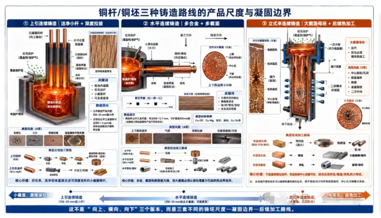
The Real Choice Is Not the “Casting Direction,” but the Billet Scale, Solidification Boundary, and Subsequent Processing Route
Core Perspective
First, we need to correct one of the most easily confused concepts: upward continuous casting and horizontal continuous casting can directly produce 8–30 mm level wire rods/small-section billets, while vertical semi-continuous casting mainly deals with large-section round billets, square billets, or slabs, which still require subsequent extrusion, forging, or rolling. The three are not three “horizontal, upward, and downward” versions of the same copper rod specification, but three completely different product routes.
If the final target is a conductor of 0.05 mm or even finer, a single micropore, oxide particle, or periodic drawing mark in the cast structure may be amplified into a wire breakage source after dozens of drawing passes; if the final target is an extruded copper tube, forged bar, or large-size busbar, the most important factors are no longer direct drawability, but the center density of large-section billets, segregation, surface cracks, and whether subsequent hot processing can completely break down the cast structure. Therefore, before discussing “which continuous casting method is the best,” the required billet form must first be determined by working backward from the final product.
I. First Put the Three Processes Back into Their Correct Positions: They Do Not Produce the Same “Copper Rod”
The crystallizer of upward continuous casting is inserted into the liquid copper from above the molten pool, and the solidified rod billet is pulled upward. Because the liquid surface can be covered and protected, the cast rod does not need to experience open pouring and falling flow processes. This route is particularly suitable for oxygen-free copper wire rods. UPCAST’s publicly available technical materials identify high-quality oxygen-free copper rods as a core product, with typical publicly available product ranges covering 8–20 mm. Official materials describe UPCAST oxygen-free copper as having oxygen content below 3 ppm; in public process discussions on high-conductivity oxygen-free copper 8 mm rods, the typical target can even be below approximately 2.5 ppm.[1-3]
Horizontal continuous casting allows metal to be horizontally extracted through a water-cooled crystallizer/graphite mold from the side of the furnace. It can produce not only small-section wire rods but also larger bars, tube billets, profiles, or some copper alloy billets. In Rautomead’s publicly available redraw rod equipment materials, conventional horizontal wire rod sizes are approximately 8.0–12.7 mm and can be extended to approximately 30 mm; meanwhile, its publicly available technology has long been applied to the continuous casting of Cu-Mg, bronze, and other copper alloys.[4-6]
Vertical semi-continuous casting represents another type of problem. Molten metal enters a water-cooled crystallizer, the billet is pulled downward, and after leaving the crystallizer it usually continues to receive secondary water spray cooling. Due to equipment stroke, casting pit depth, and limited single casting length, it generally produces large-section billets of a certain length rather than continuously coiled small wire rods. For copper and copper alloys, such billets are more commonly used as mother billets for subsequent extrusion, forging, or rolling processes.[7,11,12]
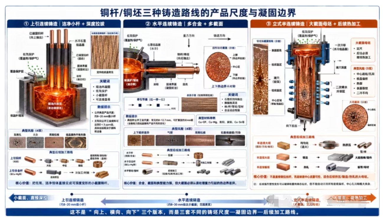
II. Upward Continuous Casting: Most Suitable for Bringing “Melt Cleanliness” Directly into Fine Wire Drawing
The real advantage of upward casting is not simply “pulling upward.” Its key lies in the direct coupling between the crystallizer and the molten pool. Liquid copper enters the crystallizer under protection conditions, and after the cast rod is formed, it is directly pulled upward and coiled. For oxygen-free copper, this means that the process can avoid new oxidation opportunities caused by open pouring. As long as cathode copper purity, molten metal residence time, covering, furnace atmosphere, and crystallizer conditions are properly controlled, stable redraw rods with low oxygen content, high conductivity, and relatively clean surfaces can be obtained.[1-4]
This route is particularly suitable for fine wire drawing processes that require large total strain. Oxygen-free copper does not have the Cu₂O-based grain boundary/eutectic oxide system characteristic of ETP copper, so during fine drawing it is less likely to experience local stress concentration caused by undeformable hard oxide particles. However, “low oxygen” does not mean that the melt is naturally clean. UPCAST’s own public materials particularly emphasize hydrogen and micropores: high-hydrogen melts may form micropores during solidification, so the proportion of recycled material, melt exposure, holding time, degassing/protection, and other factors also determine the final drawing performance.[3]
From a structural perspective, upward cast rods usually form obvious directional columnar crystals or grains extending along the pulling direction. For subsequent cold drawing, this structure is not a defect; as long as the center is dense, grain boundaries are clean, and there are no coarse inclusions, subsequent large deformation will continuously elongate and refine the grains. Research on Cu-Cr-Zr, Cu-Cr-Ag, and Cu-Sn alloys even utilizes the columnar crystal structure formed by upward casting, followed by continuous extrusion, cold deformation, and aging design to ultimately achieve the desired balance of strength and conductivity.[8-10]
The most sensitive parameter in upward casting is whether the “solidification front can remain stably at the correct position.” If the pulling speed is too high, the liquid core length increases and the shell thickness becomes insufficient; if it is too slow, productivity decreases and local thermal balance may also change. In simulations of upward casting of Cu-0.45Sn, casting speed was proven to have a significant influence on liquid core length. Within the research window for 20 mm billets, the recommended upward pulling speed was no higher than approximately 25 cm/min. At the same time, stop-pull rhythm and primary cooling water volume also affect surface and internal defects.[9] This value only applies to that alloy and equipment, but it demonstrates that upward casting is not simply “pulling at a constant speed,” but a solidification system jointly controlled by speed, stop-pull operation, water cooling, and superheat.
Products better matched with the upward casting route
High-conductivity oxygen-free copper fine wires, enameled wires, flexible stranded wires, ultra-fine wire mother rods, and some dilute copper alloys requiring direct transition from small-section cast rods into continuous extrusion/drawing. The real control focus is oxygen, hydrogen, inclusions, graphite crystallizer condition, and pulling thermal balance.
III. Horizontal Continuous Casting: The Advantage Is Not “Pulling Horizontally,” but Stronger Adaptability to Alloys and Cross-Sections
The greatest engineering value of horizontal continuous casting lies in the fact that the furnace, crystallizer, and pulling system can be relatively flexibly combined according to different alloys and cross-sections. Graphite has excellent thermal conductivity, lubrication performance, and tolerance to copper alloys, so it has long been used in the continuous casting of copper, bronze, and Cu-Mg alloys. Public industrial materials show that horizontal wire rods can be produced in 8–12.7 mm redraw rod sizes, can be extended to larger diameters, and can also produce bars, tube billets, and profiles by replacing crystallizers.[4-7]
However, horizontal arrangement introduces a physical issue that is less prominent in upward casting: the gravity direction coincides with the upper and lower directions of the cross-section. For larger bars, hollow billets, or products with significant solidification shrinkage, liquid metal flow, the position of the solid-liquid interface, and the mold-wall air gap may create differences between the upper and lower surfaces. Research on horizontal continuous casting copper alloy tube billets has observed differences in microstructure and properties between the upper and lower regions, caused by differences in circumferential heat transfer, air gaps, and solidification conditions.[7,13] Therefore, as the cross-section becomes larger, horizontal casting cannot rely only on “average cooling water volume” to determine quality.
Horizontal graphite mold continuous casting also frequently adopts periodic pull-stop or pull-stop-reverse control to maintain the solidified shell, reduce sticking to the mold, and obtain stable surfaces. This rhythm itself creates periodic thermal history on the surface and near-surface regions. Therefore, pulling cycles, mold temperature, cooling water, and melt level must be properly matched. Crystallizer wear, graphite quality, installation concentricity, and the chemical affinity between copper alloys and carbon may also become issues related to service life and contamination; for certain copper alloys with high carbon affinity, public patents have even adopted ceramic or non-reactive materials to replace or cover graphite working surfaces.[15]
Therefore, the horizontal method is particularly suitable for factories with “many product types, many alloys, and many cross-sections,” but its quality management must extend from simple chemical composition control to upper/lower structural symmetry, periodic drawing marks, mold wear, and solid-liquid interface position. For products that will subsequently undergo continuous extrusion, rolling, or moderate drawing, these cast-state characteristics can often be significantly improved through later deformation; for products directly entering ultra-fine wire drawing, it is necessary to more strictly evaluate whether cast-state defects will be inherited.
Products better matched with the horizontal casting route
Cu-Mg, bronze, brass, and various small-section copper alloy rods/tube billets/profiles, as well as continuous casting applications requiring frequent changes in specifications and alloys. Its greatest advantage is adaptability to cross-sections and alloys, while its greatest risks are thermal boundary asymmetry caused by gravity and periodic defects caused by graphite molds and pulling rhythms.
IV. Vertical Semi-Continuous Casting: The Real Goal Is to “Make a Good Mother Billet,” Not Directly Produce Drawing Rods
When comparing vertical semi-continuous casting with upward and horizontal casting, the most important point is to first recognize that the product scales are different. Vertical semi-continuous casting usually serves larger round billets, square billets, or slabs. Metal forms an initial solid shell inside a water-cooled crystallizer, moves downward out of the crystallizer into a secondary spray cooling zone, and finally produces large-section mother billets for extrusion, rolling, or forging.[11,12]
The core of large-section billets is not “solidification of the surface means success,” but the simultaneous control of liquid pool depth, shell thickness, center feeding, thermal stress, and secondary cooling. When cooling is insufficient, the solid shell becomes too thin and the liquid pool becomes too deep, limiting productivity and safety; when cooling is too strong, the temperature difference and thermal stress between the surface and center increase, potentially causing cracks, distortion, or more obvious structural gradients. Three-dimensional computational studies on semi-continuous copper casting have clearly identified the ratio between primary crystallizer cooling and secondary spray cooling as a key variable. Another study pointed out that for extrusion billets, pursuing the fastest possible solidification is not the only goal, because a lower solidification rate can obtain a coarser and softer cast structure, thereby reducing the load during certain extrusion stages. This conclusion does not mean “coarser grains are always better,” but rather reminds us that the optimal cast structure should serve the next hot-working process.[11,12]
For copper alloys containing alloying elements, large-section semi-continuous billets must pay particular attention to dendritic segregation and the center region. Microsegregation can be significantly reduced through subsequent homogenization and hot working, but macrosegregation, center porosity, and coarse inclusions do not automatically disappear through subsequent rolling. Therefore, quality evaluation of vertical semi-continuous casting must include macrostructure, center density, chemical composition uniformity along the cross-section and length, as well as cracks and surface layers, rather than relying only on electrical conductivity and surface appearance.
This is also why many high-performance copper alloy bars, tubes, and large-size profiles are still willing to first produce large billets and then use hot extrusion or forging to break down cast dendrites and segregation structures. Compared with directly casting 8–20 mm wire rods, this approach adds one or even several high-cost hot-working steps, but in return provides stronger structural reconstruction capability.
Products better matched with the vertical semi-continuous casting route
Copper and copper alloy products requiring large-section mother billets and subsequent extrusion, forging, or hot rolling. The goal here is not “direct drawability,” but a dense center, controlled segregation, crack-free surface, and a stable base material for subsequent hot processing.
V. Putting the Three Routes in the Same Table Reveals Their Real Differences
| Comparison Dimension | Upward Continuous Casting | Horizontal Continuous Casting | Vertical Semi-Continuous Casting |
|---|---|---|---|
| Typical product scale | Small-section rods, publicly available industrial cases commonly 8–20 mm | Small-section rods commonly 8–12.7 mm, expandable to approximately 30 mm and other cross-sections | Large-section round billets/square billets/slabs, size determined by equipment and subsequent processing |
| Billet state | Continuously pulled upward, can be coiled | Horizontally pulled, can be coiled or cut to length | Pulled downward, forming finite-length large billets in each casting cycle |
| Typical materials | Cu-OF, dilute copper alloys | Cu-OF, Cu-Mg, bronze/brass, and various copper alloys | Pure copper and various copper alloys requiring large billet hot processing |
| Solidification/thermal boundary characteristics | Crystallization in molten pool, strong directionality, good protection conditions | Side extraction through graphite mold, gravity amplifies upper/lower thermal boundary differences | Primary crystallizer + secondary spray cooling, large liquid pool and large-section thermal stress are key concerns |
| Cast structure | Columnar/directional grains commonly appear | Changes with alloy, mold, and casting rhythm; large sections require attention to upper/lower differences | Dendritic and columnar/equiaxed regions coexist; center and surface differences are more important |
| Most sensitive defects | Hydrogen microporosity, inclusions, drawing marks, crystallizer thermal balance instability | Upper/lower structural differences, air gaps, periodic drawing marks, mold wear/contamination | Center looseness/segregation, hot cracking, surface cracks, uneven secondary cooling |
| Typical subsequent route | Direct multi-pass drawing/continuous extrusion | Drawing, continuous extrusion, rolling, machining | Homogenization → extrusion/forging/hot rolling → subsequent precision processing |
| Core advantage | Clean low-oxygen small rods suitable for deep drawing | Flexible alloys and cross-sections, strong changeover capability | Strong compatibility with large billets and subsequent hot processing |
| Goals that should not be simplified | Do not mistake “low oxygen” for zero porosity or zero inclusions | Do not ignore upper/lower structural differences by only looking at average structure | Do not directly compare it with 8 mm drawing rods in terms of surface quality/coiling efficiency |
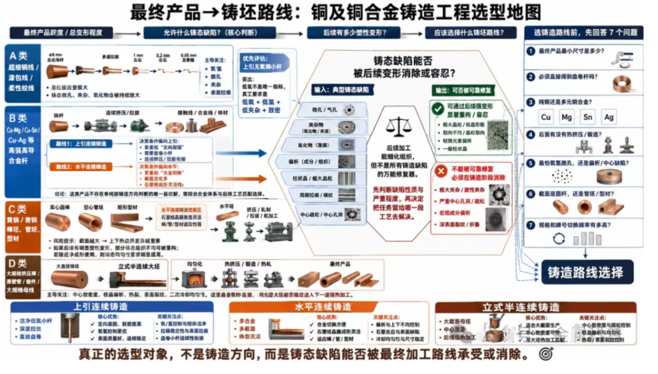
VI. Four Real Product Scenarios: The Route Selection Is Actually Not That Difficult
Scenario 1 is high-conductivity oxygen-free copper fine wires, enameled wires, and flexible stranded wires. The finer the final product, the greater the total drawing strain, and the more easily micropores, inclusions, and local oxides in the cast rod become sources of wire breakage. In this case, upward continuous casting of oxygen-free copper rods is the most targeted solution: it directly connects clean low-oxygen molten metal with small-section cast rods, which can then enter large drawing, medium drawing, and fine drawing processes. The real focus is not pursuing a “thinner cast rod,” but eliminating hydrogen, oxygen, inclusions, and crystallizer instability.
Scenario 2 is Cu-Mg, Cu-Sn, Cu-Ag, and other contact wire/high-strength high-conductivity alloy rods. Both upward and horizontal routes can be suitable, and they cannot be generalized. If the alloy system is compatible with graphite molds and frequent specification or cross-section changes are required, the horizontal method provides strong flexibility; if more emphasis is placed on directional solidification, small rod coiling, and connection with subsequent continuous extrusion/drawing, upward casting also has mature examples. The real comparison should focus on element loss, segregation, graphite reaction, cast rod surface quality, and subsequent deformation, rather than the casting direction itself.[5,6,9]
Scenario 3 is brass, bronze tube billets, or larger bar billets. In this case, horizontal continuous casting is usually easier to use with different graphite crystallizers to obtain bar, tube, or profile cross-sections. However, the larger the cross-section, the more seriously the upper/lower thermal boundary differences must be addressed. If extrusion/rolling follows, some cast-state structural non-uniformity can be repaired through plastic deformation; if near-net-shape use is required, the requirements for cast-state uniformity must be significantly increased.
Scenario 4 is large-size copper alloy extrusion bars, thick-wall tubes, or forgings. In this case, vertical semi-continuous casting is usually more consistent with the process chain because what is truly needed is a large billet that can undergo stable hot processing. Controlling center defects, dendritic segregation, and surface cracks in large billets is far more important than direct coiling capability. Only through subsequent homogenization, extrusion, or forging can the structure be reorganized to obtain the refined structure and properties required in the final product.
VII. Before Selecting a Continuous Casting Route, Enterprises Should Answer at Least These Seven Questions
| Question | Why It Matters | Impact on Route Selection |
|---|---|---|
| What is the minimum final wire diameter/size? | Determines total deformation amount and the degree to which cast-state defects are amplified | Ultra-fine wires favor clean small rods; large-size products can accept large billets + hot processing |
| Is a coiled rod billet required? | Determines post-casting logistics and whether direct drawing is possible | Upward/horizontal small rods have obvious advantages; semi-continuous casting generally produces fixed-length large billets |
| Is the material pure copper or multi-element copper alloy? | Determines oxygen control, segregation, graphite compatibility, and element loss | Oxygen-free copper tends toward upward casting; complex alloys require comparison among upward/horizontal/large billet routes |
| Is there subsequent hot extrusion/forging? | Determines whether cast structure has an opportunity to be completely reconstructed | With strong hot processing, larger mother billets can be accepted; direct fine drawing requires stricter cast quality |
| What is the greatest concern: oxygen/hydrogen or segregation/center defects? | Different processes have different dominant defects | OF fine rods focus on melt cleanliness; large billets focus on center quality and secondary cooling |
| Is the product cross-section complex? | Rods, tubes, and profiles have different requirements for molds and pulling structures | Horizontal graphite molds usually provide greater cross-section flexibility |
| What are the annual output and frequency of grade changes? | Determines furnace, crystallizer quantity, and changeover cost | The optimal equipment differs between high-frequency alloy/specification changes and large-scale single-product production |
After selecting the route, what should truly be established is a process loop of “melt—crystallizer—pulling—cooling—cast quality.” Regardless of the process, it is recommended to continuously record at least:
-
melt temperature and liquid level;
-
O/H content and major alloying elements;
-
crystallizer/graphite sleeve service life;
-
cooling water inlet temperature and flow rate;
-
casting speed or stop-pull rhythm;
-
cast rod surface defect rate;
-
macrostructure/porosity;
-
electrical conductivity;
-
downstream drawing breakage rate.
The final judgment of whether a casting line is good should not only depend on “how many tons it can produce,” but on how many defects it carries into the next process.
VIII. Conclusion: Do Not Ask “Upward, Horizontal, or Downward”; First Ask How This Copper Will Be Deformed Eventually
The essential difference between upward, horizontal, and vertical semi-continuous casting does not lie in direction, but in the thermal boundaries where the solidification front exists, the product cross-sectional scale, and whether strong plastic deformation will occur after casting. Upward casting is best at directly converting clean low-oxygen molten metal into small rods suitable for deep drawing; horizontal casting is best at achieving manufacturing flexibility among multiple alloys and cross-sections; vertical semi-continuous casting focuses on the center quality of large-section mother billets and their compatibility with subsequent hot processing.
Therefore, if the final goal is to produce copper wires of several tens of micrometers, the selection logic should start from “which route introduces the fewest pores, inclusions, and oxides into multi-pass drawing.” If the final goal is large-size rods, tubes, or forgings, the logic should start from “which large billet is most suitable for subsequent extrusion/forging to reconstruct the structure.” Working backward from the final processing route is usually more reliable than comparing casting machine output, price, or so-called advanced level.
One-sentence summary
For directly producing high-cleanliness small rods and deep drawing, prioritize evaluating upward casting; for multi-alloy, multi-cross-section small billets and rod/tube/profile products, focus on comparing horizontal and upward casting; for large-size extrusion, forging, and hot-rolled mother billets, focus on vertical semi-continuous casting. The true selection target is whether the cast-state defects can be tolerated or eliminated by subsequent processes.
References and Public Technical Materials
[1] UPCAST OY. UPCAST® Continuous Casting Technology. Technical brochure, 2023/2025 edition.
[2] UPCAST OY. UPCAST® Technology: oxygen-free copper rod and tube continuous casting. Official technical documentation.
[3] UPCAST OY. Casting High-Conductivity Oxygen-Free Copper Rod from Scrap: Myths and Reality. Technical article.
[4] Rautomead International Ltd. Quality Production in Copper Re-Draw Rod. Technical paper.
[5] Rautomead International Ltd. Continuous Casting of Dilute Copper Alloys for Drawing to Fine Wire. Wire Association International technical paper, 2019.
[6] Rautomead International Ltd. Graphite Continuous Casting Technology. IWCC Technical Seminar, Barcelona, 2009.
[7] Tavolzhanskii S. A., Pashkov I. N. Features of the Continuous Casting of Small-Section Billets from Copper-Based Alloys. Metallurgist, 2021, 64(9-10):1068-1076. DOI:10.1007/s11015-021-01088-y.
[8] Chen J., Xiao X., Yuan D., Guo C., Huang H., Yang B. Microstructure and properties of Cu-Cr-Zr alloy with columnar crystal structure processed by upward continuous casting. Journal of Alloys and Compounds, 2021, 889:161700. DOI:10.1016/j.jallcom.2021.161700.
[9] Hua S., Zhang P., Liu Z., Lu C. Numerical simulation of the solidification process of Cu-0.45%Sn alloy in upward continuous casting. Materials Research Express, 2021, 8:096532. DOI:10.1088/2053-1596/ac2696.
[10] Liang D., et al. Relationship between Microstructure and Properties of Cu-Cr-Ag Alloys Prepared by Continuous Updrawn Casting, Continuous Extrusion, Cold Rolling and Aging. Materials, 2020, 13:732.
[11] Hameed A. H., Mohammed A. A., Fadhil O. T. Effect of Cooling Intensity and Position on Solidification in Semi-Continuous Casting of Copper. Open Journal of Fluid Dynamics, 2016.
[12] Hameed A. H. Optimization of Secondary Cooling Percentage during Semi-Continuous Copper Casting Process. Computational Thermal Sciences, 2017, 9(3):213-225. DOI:10.1615/ComputThermalScien.2017017197.
[13] Ebrahimzadeh I., Hossein Akbari G. Microstructure and mechanical properties of horizontal continuous cast pipe of CuZn40Al1 alloy. International Journal of Cast Metals Research, 2008, 21(5):394-400. DOI:10.1179/136404608X320724.
[14] Mahmoudi J., Vynnycky M., Sivesson P., Fredriksson H. An Experimental and Numerical Study on the Modelling of Fluid Flow, Heat Transfer and Solidification in a Copper Continuous Strip Casting Process. Materials Transactions, 2003, 44(9):1741-1751. DOI:10.2320/matertrans.44.1741.
[15] US20060070716A1. Method and system for continuously casting copper alloys. (Regarding crystallizer/protective material selection for copper alloys with high carbon affinity.)
Note: The numerical values such as dimensions, speeds, and oxygen content mentioned in the article come from specific publicly available equipment, papers, or industrial cases. They are only used to illustrate process windows and route differences and should not be directly applied as universal production standards without considering alloy composition, crystallizer structure, cooling capacity, and final product requirements.
-
Tel:
-
E-mail:
-
Address:
No.1 Chengxi West Road, Cicheng, Ningbo, China
-

Ms.Yu
-

Ms.Sun